skip to main |
skip to sidebar
This is how I keep my tools at hand when I am cruising in my creeper.
I made this handy item from a half-sheet baking tray and four casters that I purchased at Lowes. I used Pop rivets to attach the casters to keep the profile of the fasteners as low as possible. It has a lot of strength due to the commercial nature of the tray and is very light because of the aluminum construction. The approximately 3/4 inch sides keep tools and other items from falling off.
 You are welcome to email me with questions and comments.As always you can see larger versions of all of the blog photos at my Flickr site.
Enjoy the Ride!
If you remember from a previous posting (Oct 14), I cleaned and reassembled a recently acquired steering box with synthetic lube and the addition of a new sector shaft seal. No other parts were replaced.The steering box was installed in the truck with new bolts and they were torqued to the proper setting. The pitman arm and drag link were installed, torqued and the cotter pins were installed and then.....
A New Old Stock (NOS) steering shaft assembly was listed on eBay!
 The above photo is from the eBay listing.
Always looking for ways to improve the truck prompted me to bid. I was the winning bidder using my sniping software and now it was time to remove the steering box, the one that was already installed! So out came the steering box and it was disassembled...again.
The new steering shaft arrived and the grease was so old that the worm would not turn. It was totally frozen. I submerged the assembly in mineral spirits for a couple days and eventually I got it apart.
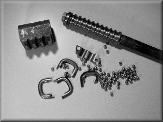
There was still some dried grease that had to be removed so out came the Dremel with a brass brush to clean the gears and ball returns.Some of the photos in this entry are in grayscale instead of color. I had the camera on the wrong white balance setting and no amount of color correction would work.The photo below shows all of the components, steering shaft, ball nut, return guides, clamp, screws and balls cleaned and ready to go....
This is a job that anyone can do! I never went this deep into a steering box before but it really is quite simple and definitely not "brain surgery!"
After putting the ball nut on the steering shaft it is necessary to install the balls, all 62 of them. There are two circuits of 31 balls each so they have to be carefully counted and divided. 20 balls are dropped into one hole of the ball nut. The shaft is slowly turned as the balls are dropped into the hole until 20 balls are swallowed up.
 There are two ball return guides that consist of two halves. Refer to the first photo which shows all of the components.
The remaining 11 balls for the first circuit are put into a return guide half section using grease to hold them in place.
The other half section of a ball return guide is placed over the balls in the grease-filled half. The assembled ball return guide is then placed into the guide holes of the ball nut.
The second circuit is filled using the same method as the first circuit. When all of the balls are installed, the second ball return guide is filled with the remaining balls and installed.

The ball return guide clamp is placed over the ball returns and the two screws are installed. Now that you see how easy the job is I am sure that anyone can do it. It just takes some patience.
If you ever attempt to go this deep into a steering box, I recommend that you have lots of paper towels and rags to clean the greasy mess. Make sure that you have a half sheet baking pan or something similar to catch all of the small parts. Don't lose any of the balls!

In the above photo you can see what a brand new gear looks like. There is no gauling on the teeth. Usually, gauling on these teeth indicate that the sector gear was over tightened to remove free play.I reassembled the steering box using Green Grease and another new sector shaft seal. I installed the steering box (photo below) and reinstalled the pitman arm and drag link.Wow! What a difference! There is no free play at all now. There are no tight spots going from full left to full right. This truck is going to drive like new!

Be sure to vote in the poll that relates to this Steering Box story.
As always, there are larger versions of these photos at my Flickr site in the "Steering Box" Set. Just make sure you use your browser's "Back" button to return to this page. I don't want you getting lost in cyberspace!
The parking brake assembly was a quick and easy restoration. It was simply washed, blasted and painted. Even with three coats of lacquer you can see how rusty it was. It now has three coats of black lacquer to protect it. The shaft and ratchet pieces were finished in clear from Eastwood.
 As always, there are larger versions of these photos at my Flickr site in the "Econoline Brakes" Set. Just make sure you use your browser's "Back" button to return to this page. We don't want you to get lost in cyberspace!
This is a long entry with twenty smaller photos so that it loads quicker. You can click on the photos for larger versions or visit my Flicker site for even larger versions of these same photos. Just make sure you return to this page to see the rest of the blog!This job was not that hard to do. Was it messy? Yes. There was also the smell of 40 year old lube which I found unpleasant.If you are considering whether or not you should disassemble your steering box....go for it! Do like I did and have some items close at hand....disposable vinyl gloves (at least 20), C-fold paper towels or a roll with the towels ripped and stacked, rags and a lined garbage can to drop the greasy towels and rags into. Mineral spirits and brake cleaner are helpful.I find it is always helpful to have a commercial aluminum baking sheet pan or half sheet pan to put under the item being worked on. That will keep the removed parts from wandering and keep the bench clean. Commercial aluminum baking sheet pans are available at restaurant supply stores for a few dollars. I clean them with either brake cleaner or soap and water.These pans have many uses....under axle hubs when doing brake jobs, taking things apart so small parts don't get lost, etc. Below are the components of an early Econoline steering box. Missing from the photo are the sector shaft seal, lower bearing race, filler plug and adjusting screw lock nut.
 This is the ball nut on the steering shaft. The U-shaped pieces (ball return guides) are made in two halves and they contain steel balls. On the inside of this ball nut are additional balls for a total of 62. This is a "Recirculating Ball" steering gearbox as opposed to a "Rack and Pinion" steering gear box.
 The side cover has three mounting bolt holes and a threaded hole for the sector shaft adjusting screw.
 Inside the side cover is a bushing with lubrication grooves. Notice the scratches probably caused by lack of lubrication and pitting on the sector shaft. The pitting was probably caused by moisture contamination of the old lubricant.
 The sector shaft showing the signs of age. Notice the pitting and scoring and the grooves cut by the seal. I polished the shaft with emery cloth and 1000 grit paper but most of the defects will have to remain.
 This is the empty steering box. I cleaned all of the original grease out of it. No other changes were made except for a new sector shaft seal.
 An inside view of the steering box. The race for the lower bearing for the steering shaft is center, left. The bushing for the output end of the sector shaft is right, bottom.
 New synthetic chassis lube was applied to the worm gear and worked into the interior of the nut.
 Notice the galled surface of the tooth in the center of the photo below. It was probably caused by over-tightening of the sector shaft's adjusting screw. You can also see the taper of the teeth.The reason that "play" is removed when the adjusting screw is tightened is because the sector's teeth are pushed deeper into the taper.
 The lower bearing of the steering shaft is installed into the steering box and packed with lube. A portion of the bearing is visible on the left of center.
 The steering shaft with nut is installed into the steering box.
 The proper setting of the steering shaft bearing adjuster (marked with a light gray/green dot) is to measure the preload with an in-lb torque wrench to 4 - 5 inch pounds.I made the adjustment by tightening the bearing adjuster by hand. I made the adjustment so that after there was no play in the shaft, I tightened it a bit more. Call me a "human torque wrench!"The lock nut (marked with a dot of red paint) is tightened with a drift and hammer to insure the position of the bearing adjuster does not move.
 The inside of the steering box filled with lube.
 The Ford Shop Manual calls for a different method of assembly from this point on. They want the sector adjusting screw and shim installed on the sector followed by the side cover. This assembly is supposed to be installed as a single unit.I decided a better method would be to fill the inside of the steering box with as much lube as possible with the sector installed.
 I then installed the adjusting screw and shim onto the end of the sector and packed even more lube into the remaining cavities.
 The inside of the side cover is coated with lube and a new homemade gasket is installed. When the cover was installed, lube squeezed out to further insure no air pockets were left in the box.
 Below, the adjusting screw is visible entering the side cover's threaded hole. The side cover attaching bolts are then installed finger tight.The adjusting screw is turned counter-clockwise to draw it into the cover. There must always be lash between the ball nut and sector gear teeth during this process.Continue backing the adjusting screw out while finger tightening the attaching bolts. When the side cover is making contact with the steering box, make sure there is still some lash between ball nut and sector gear teeth.Then and only then can the mounting bolts be tightened with a torque wrench to 15 to 22 foot pounds. The lock nut for the adjusting screw can be installed but not tightened at this time. The mesh load is then set and the lock nut tightened. It is a lot easier to do than it takes to read all of the steps!
 The steering box is ready to be installed. If any other adjustments are necessary they can be made after the drag link is installed.
 The steering box is now ready to install! Yippee!